Operation - Aqua-Filter™ Stormwater Filtration System
The Aqua-Filter™ treatment train is designed to provide a high level of water quality treatment through the use of a swirl chamber (Aqua-Swirl™) for pretreatment followed by a filtration chamber for secondary treatment. The offline Aqua-Filter™ configuration uses a separate diversion structure, or weir device located upstream of the unit. The diversion structure is designed to direct only the designed water quality treatment flow through the Aqua-Filter™ system. Twin or multiple Aqua-Filter™ system configurations can be implemented to allow for higher treatment flow capabilities beyond that of a single unit.
The two treatment steps of the Aqua-Filter™ operation are described below.
Step 1. Pretreatment
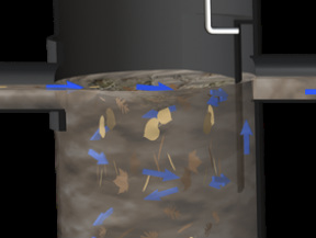
Operation begins when stormwater enters the Aqua-Swirl™ by means of its tangential inlet pipe thereby inducing a circular (swirl or vortex) flow pattern. The swirl chamber provides pretreatment for filtration treatment by capturing and retaining coarse sediment, debris and free floating oil. A combination of gravitational and hydrodynamic drag forces results in solids dropping out of the flow. Particles settle and migrate to the center of the swirl chamber floor where velocities are the lowest. The captured (settled) particles are retained in a cone shaped sediment pile at the base of the swirl chamber. The treated flow exits the swirl chamber behind an arched inner baffle that is positioned opposite the influent pipe and in front of the effluent pipe. The top of the baffle is sealed across the treatment channel to eliminate floatable pollutants from escaping the swirl chamber. A vent pipe is extended up the riser to expose the backside of the baffle to atmospheric conditions, thus preventing a siphon from forming at the bottom of the baffle. Water is retained within the swirl chamber between storm events to a level equal to the invert elevations of both the influent and effluent pipes.
Step 2. Filtration
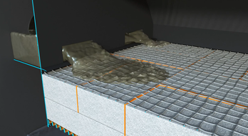
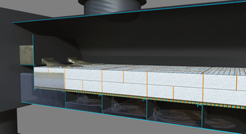
As pretreated water enters the filtration chamber, it is evenly distributed across the horizontal filter bed and allowed to permeate downward through the filter media under gravity flow conditions. While downflow filtration designs are most commonly used, custom upflow designs can be used where there is little vertical difference between the inlet and outlet elevations.
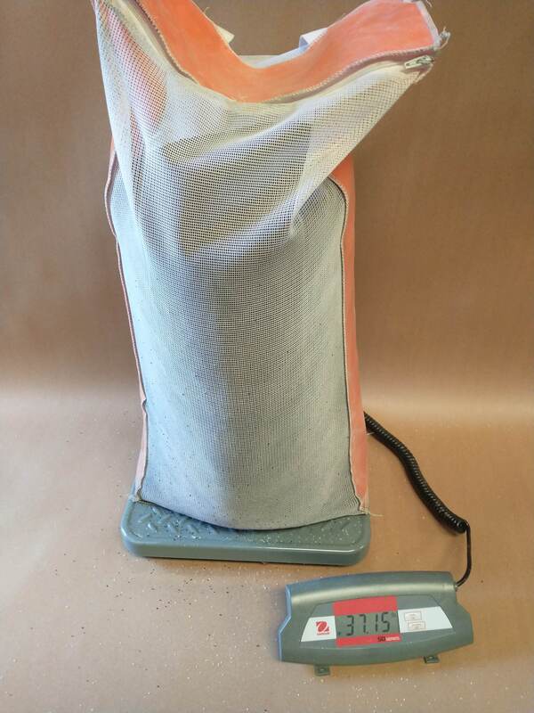
The filtration chamber utilizes a number of filter media rows based on the specified treatment capacity. Each filter media container measures two feet (0.6 meters) long, one foot (0.3 meters) wide, and 0.5 feet (0.15 meters) thick, providing for an area of two square feet (0.18 square meters) and a volume of one cubic foot (0.027 cubic meters). The filter containers are stacked one on top of another in an alternating configuration such that each filter row is one foot (0.3 meters) thick. Each row of filter media contains 12 filter containers and occupies an area of 12 square feet.
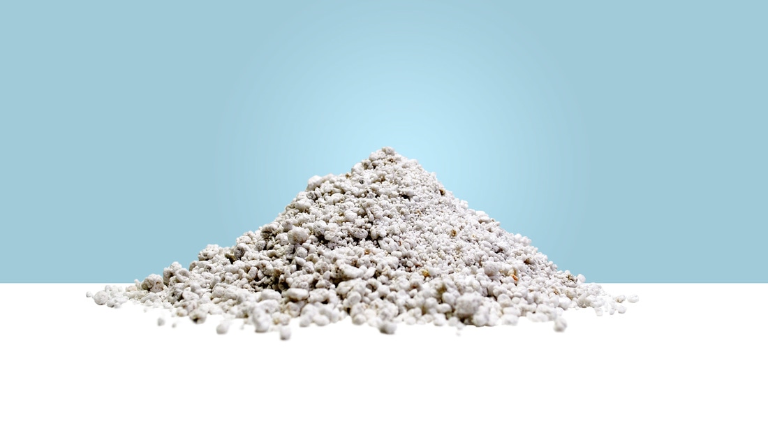
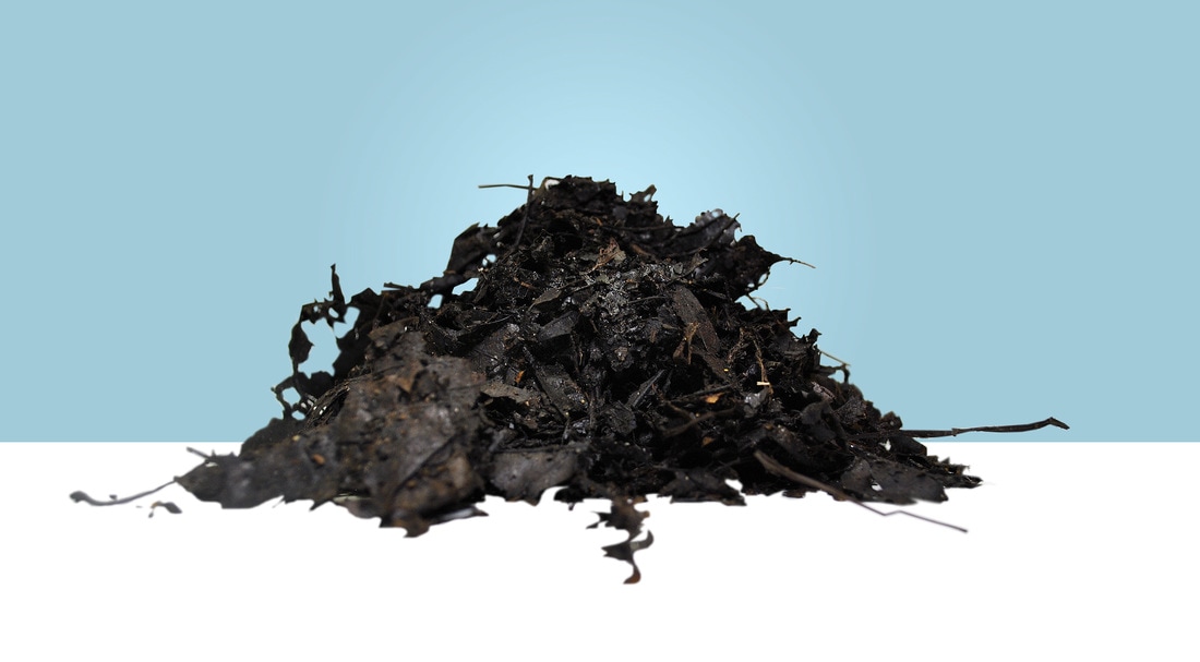
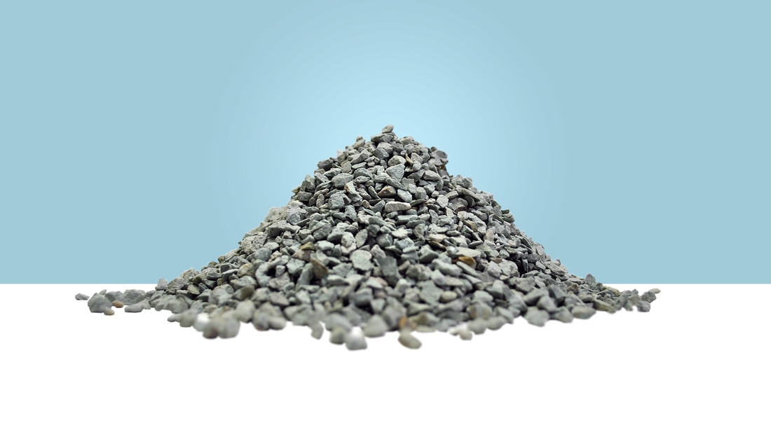
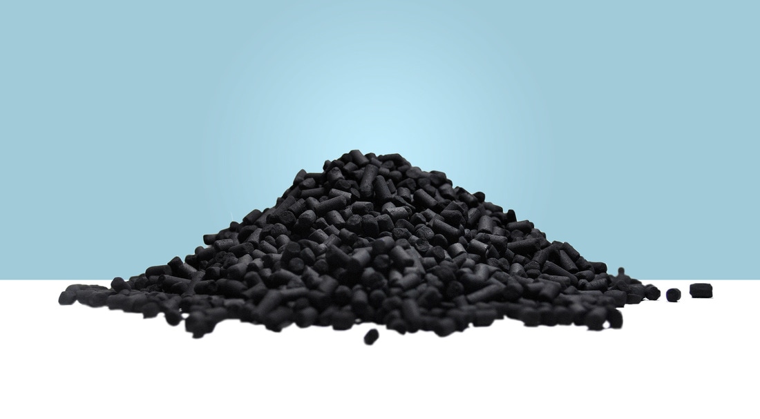
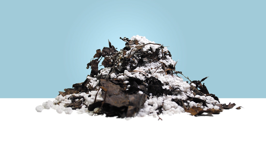
The filter media is capable of removing fine-grained sediment, heavy metals when bound to particulate matter and residual oil. Perlite is the most commonly used filter media in the Aqua-Filter™. Other filter media such as granular activated carbon (GAC), leaf compost, zeolite and various media blends are also available to meet site-specific discharge criteria.